A deep dive into the concepts shared in the recent webinar on “Tools to Integrate AirFuel Resonant in Your Product,” by Ky Sealy, Senior Principal Engineer at WiTricity Corporation.
This webinar explained the principles and technology of magnetic resonance wireless power and introduced some useful tools to help you build a product with AirFuel Resonant.
You can watch the webinar recording here: Webinar Recording
This Webinar Addresses the Following Topics:
- Principles of wireless power, and the differences between induction and magnetic resonance
- How to test systems and create an interoperable ecosystem
- Helpful tools from AirFuel that make magnetic resonance easy to integrate into your product, without having to be an expert
Principles of Wireless Power
Nikola Tesla was an innovative inventor, scientist, and creator who worked on wireless power at the turn of the 20th century. Tesla is often considered the father of modern distributed AC electricity, and due to his work, we have all of the modern wires that power our household and our businesses today. Even though some of these early wireless power concepts were not entirely practical, they are important to the fundamentals of wireless power that we use today.
If we were to break it down to a real simple set of basic physics, there are two laws that are about wireless power. There is Ampere’s Law, which states that a current in a wire produces a magnetic field. You can see in the figure below – the picture is what we call the right hand rule.
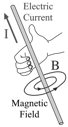 So your thumb is like the current, and the fingers that go around the current are how the magnetic field would shape when you have current going in one direction. As you alternate that current going back and forth, the field goes in opposite directions.
This is important because it enables the second law of wireless power – Faraday’s Law. Faraday’s Law says that an AC magnetic field produces a current or voltage in the coil. We can use this law to help us create wireless power. In the next figure, you see a picture of what these field lines may look like. A coil will operate in a shape like a water fountain, going back and forth.

These are the principles of wireless power.
Note: Figure sources for right-hand rule and primitive WPT diagram:
- http://hyperphysics.phy-astr.gsu.edu/hbase/magnetic/magcur.html
- https://en.wikipedia.org/wiki/Wireless_power_transfer
The Differences Between Induction and Magnetic Resonance
 When we think of a toothbrush on a stand that powers up, that technology is based on wireless induction. Our phones (Qi) are also based on wireless induction, but induction wireless power transfer requires precise alignment and close placement because it requires the majority of the magnetic flux to be captured by the receiver. As a result, it needs high coupling. That high coupling doesn’t allow for the true freedom of wireless power. Some have tried and ultimately failed to give true spatial freedom to a range of existing products.
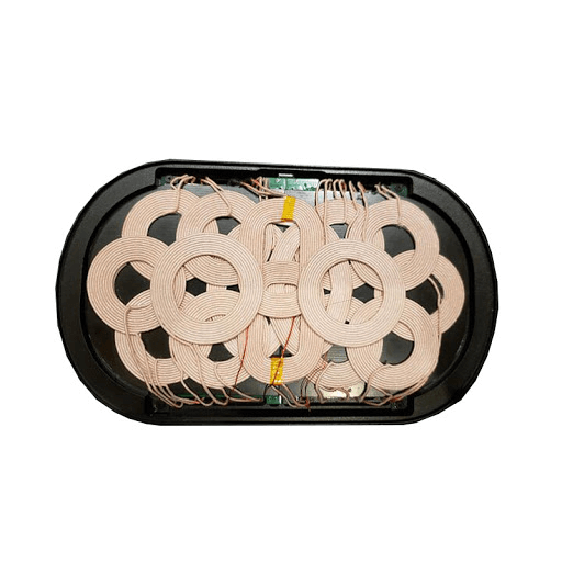 If you look closely at this product picture, you’ll see it’s a bunch of coils and it’s trying to operate by providing that spatial freedom, but it doesn’t really work very well. It doesn’t work because it’s similar to pushing a child uphill in a stroller. You have to constantly be doing work and providing energy.


There has to be a better way – and that’s what magnetic resonance wireless power is all about. Wireless power 2.0 operates with low coupling, which provides spatial freedom and still allows you to have high efficiency. A small percentage of that flux, often less than 50%, is captured by a receiving device, and we can optimize this pattern and allow it to really give us spatial freedom.

This works by the physics principle of resonance. We’ve all experienced this principle in real life. When you’re on a swing on a playground, you start by putting in a fair amount of energy to get it going. Once it’s going, you can keep it going with very little energy, and the swing will continue as you pump periodically to put in the energy you need. This is very similar to how magnetic resonance wireless power works.
I have some simplified theory of operation here for you.
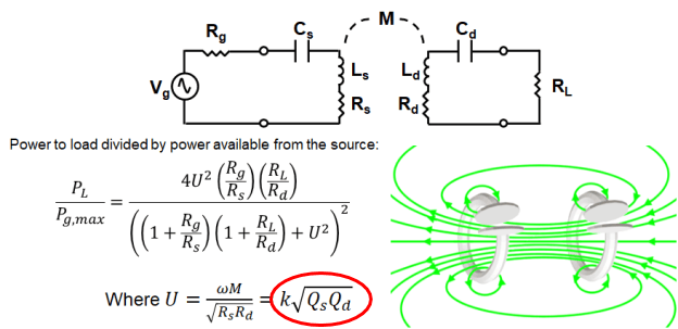
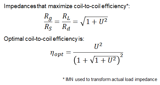
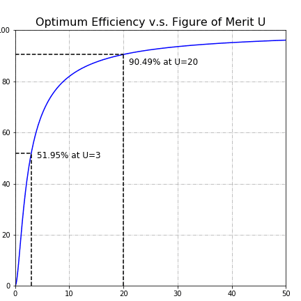
Efficiency is simply the power out divided by the power in, and it gives you a percentage of the power that’s transferred from some source to some device, or a transmitter to a receiver. If we use magnetic resonance, we can simplify with this schematic diagram. When we optimize it using the principle of resonance, and we have a low coupling factor – only a small amount of that flux is captured to allow greater spatial freedom; we can still have improved efficiency with high quality factor.  The high quality factor is what allows us to continue operating in magnetic resonance with high efficiency, and it gives you the spatial freedom all at once. We can put these factors, the coupling and the quality factor, together to create a figure of merit that we call U.
U doesn’t have to be very large. k can be very small. Q can be reasonable, just by improving our frequencies and optimizing the coil design a little bit. Out of a U of only 20, more than 90% of our power is transferred from the transmit coil to the receive coil. This is the magic of magnetic resonance, offering high quality factor with efficiency, and giving you that spatial freedom in the X, Y, and the Z height that consumers really want.
To give you an idea of how easy it is to make high quality factors, AirFuel magnetic resonance operates at 6.78 MHz. This is quite a bit higher frequency than the traditional Qi induction, which operates around 100 to 150 kHz.
This 6.78 MHz frequency has some special properties. Some of them are related to regulatory issues since it is an ISM band. And others are related to how it works physically with our coils. With 6.78 MHz, you don’t need special Litz wire, which is a very costly and expensive type of wire that is often used in wireless power transfer or other electronic components. But at 6.78 MHz, high quality factor is possible with simple PCB traces, simple copper wire, or even aluminum wire with copper plating. This is one of the great benefits at 6.78 MHz.
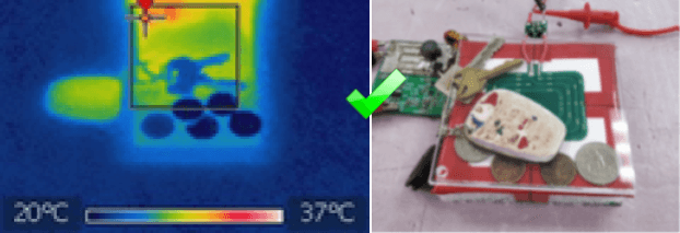
In addition, metal heating is lower at these frequencies. At 100 to 150 kHz, eddy currents in the metal heat up that metal, but as you increase the frequency, the amount of loss in nearby metals goes down with the square root of the frequency increase. As you can see from independent studies by USU (Utah State University), we’re increasing the frequency much higher, so objects such as coins and keys don’t heat up at all. That means AirFuel technology can operate and charge in the presence of metal.
Wire and Ferrite at 6.78 MHz
Both shielded designs and unshielded designs are possible with magnetic resonance. In a transmit unit, you may not need the shielding, or you may need it if you’re going to operate on a metal desk or something like that. But it is possible to use ferrite, and there are lots of ferrites that operate at 6.78 MHz. For this frequency (6.78 MHz), ferrites are typically more flexible, so you can get thinner, more flexible ferrites than what you would need at lower frequencies.
At 6.78 MHz, Litz wire is not very useful, because the strands would have to be so small that it’s difficult to make Litz wire for operation above about 1 to 2 MHz. In reality, 6.78 MHz operates very well, and you can get higher Q with simple copper wire.
AirFuel Magnetic Resonance Basics and Terminology
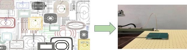
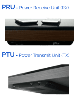 Let’s talk through some of these AirFuel Resonant terms. We have a PTU and a PRU. These are terms we’ve created to help identify the transmit side and the receive side.
If you look on the right hand side, you can see there is the TX, the PTU, is underneath a wooden table, with a fair amount of distance. And on top we have two PRUs, or receive units, like phones. They may be integrated with phones, laptops, wearables, hearables and so forth. These can be charged on top, with spatial freedom.
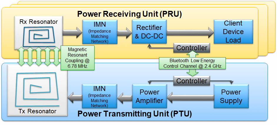
Here’s how the system works. First, there’s some sort of power supply, usually DC power. This power is converted from DC to high-frequency AC, at 6.78 MHz, using an amplifier. The current is regulated with the power amplifier, and it goes through an IMN or impedance matching network. This is the resonant portion that interacts with the transmit resonator or the PTU resonator. It’s designed in such a way that you optimize the impedances seen by that PTU, so you can most efficiently power the transmit resonator and provide the exact amount of current that is needed.
This uses Ampere’s law. It creates a magnetic field and now the PRU picks up that magnetic field using Faraday’s law. It converts into an induced voltage and current on the PRU side. Again, we use the concept of resonance in the form of an impedance matching network, using capacitors and reactive components. And we transform the impedances there, or the voltages, to loading conditions that we desire, in an efficient way, into the rectifier and in some cases a DC-to-DC converter that allows the power to be used by a client load device.
We can have more than one PRU operating at the same time, so we have this Bluetooth Low-Energy channel going on in the background that optimizes the system periodically and makes sure everything is working in the best possible way.
The great thing about the AirFuel Resonant is that it’s all backward compatible.
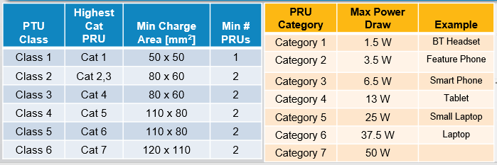
All we indicate is the maximum amount of power that a PTU can deliver. If you consider the highest class of PTU, the magnetic fields are the same throughout each of them. But at the highest class, it can power each one of the categories of the PRU from category 7, all the way down to category 1. It can power multiple of the lower categories such as multiple category 2s, multiple category 3s, or multiple phones at the same time. In short, a Class 7 PTU can support all PRUs and even multiple of the PRUs as long as the PTU maximum power is not exceeded. If the power needed by multiple PRUs does exceed the power delivery capability of the PTU, AirFuel magnetic resonance also supports Power Sharing for a seamless user experience.
Designing the System
The PTU Design
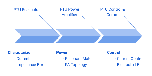
So – How do you get started designing these systems? I’ve broken it down into three simple stages of PTU design for magnetic resonance. We have the design of the PTU resonator, and we do some characterization there. Then we have the PTU power amplifier, which is what gives us the power that we need, and the AC current that’s needed to control Ampere’s law and provide power to the PRU wirelessly, via the magnetic field or the H-field. Now in addition to this, we have the PTU controls and the communications, which are based on well-known Bluetooth Low Energy.
So how does this work? First of all, we characterize the PTU resonator. We ensure that we understand what currents are acceptable for that particular PTU resonator. This can vary quite a bit, but you have the same H-field across all of the PTU resonators. If you’re a power amplifier designer, you’ll also need to understand what range of impedances will be seen by the power amplifier in order to design your amplifier.
So this is another portion of the characterization, for the PTU resonator. When you’re designing your power amplifier, you can think about how to optimize that. There are different topologies you can use, such as the class D, E, F, and so forth. Lots of books have been written about the amplifier topologies, and in combination with these amplifiers topologies, we use a resonant match in order to help optimize the operation at a given frequency. In this case, it’s 6.78 MHz.
The PRU Design
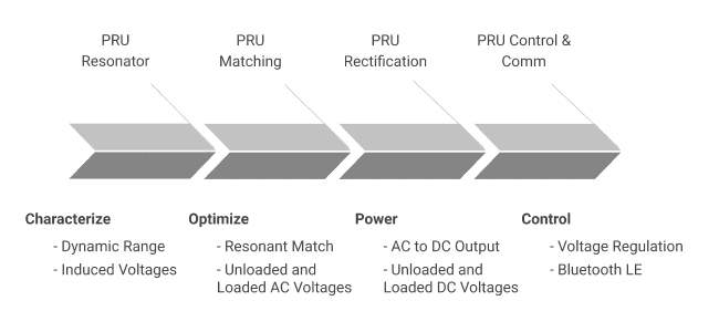
We start again with the PRU resonator. We have the matching or the IMN that’s associated with that. Then the PRU rectification, which is the conversion from the AC to DC, so it’s a useful current for our characteristic load, such as phones and laptops. Finally we have the control and communication. Now when we talk about characterizing a PRU resonator, we characterize it a little bit differently because now we’re talking about Faraday’s Law that picks up that magnetic field. Each device needs something different, so we don’t specify what your device needs. What we specify is what your device is going to get in terms of a field level, and you can specify what it needs by the design of this coil.
Dynamic range is the maximum divided by the minimum, that you’re going to see in terms of induced voltages on that coil. We also have some optimization that occurs with resonant matching. It can be as simple as a series capacitor that’s resonantly matched to your coil, that is placed inside your device, or it can be something more complicated that gives you a wide range of behaviors for your particular device. This is the resonant match, and it sets the unloaded and loaded AC voltages that you’ll see at your device. In addition, once you have that AC characteristic, you convert it through rectification to DC. Now you can characterize with a given number of rectifiers that are available. There are the simple ones, such as a half-wave or a full-wave rectifier and more complicated ones that allow you to set some voltage gains in some cases. And this provides you with your unloaded and loaded DC voltages that go to your device. You can regulate this, and of course the Bluetooth Low Energy is used out-of-band to optimize.
Ensuring Interoperability
How do we ensure interoperability across all of these devices? There are a ton of consumer devices, including wearables, laptops, hearables, and phones. They all work on the same surface, but how do we ensure this is the case? There are some common test concepts that are adopted by various first-generation standard groups. These test concepts are great for getting started in interoperability, but they don’t allow a lot of flexibility.
You have transmitters and receivers – your PTUs and PRUs. One way to ensure interoperability is to limit your design cases and limit the types of PTU resonators and PRU resonators that are allowed. If you look at the various Qi coils that are available, they all look fairly similar, and there’s a reason for that – but in doing this, it limits the innovation and use cases for the application.
The second method is to restrict to a fixed number of PTU designs, but there are a lot of different kinds of receivers, so we’ll limit the PTUs by design criteria. In this way, we get lots of use cases by allowing a wide range of receivers. However you want to design your receiver is fine, as long as it meets certain conformance criteria and demonstrates interoperability.
With this method, you have to test all of your receivers against all of your transmitters. If there are only a few, that’s not too big of a deal. When we started out as the A4WP, Alliance for Wireless Power, which eventually became AirFuel, we didn’t anticipate so many unique use cases on the transmitter side. Having lots of test cases makes it difficult for PRUs to pass testing. So we created a criteria set and said all PTU resonators that are similar to each other should not be added to our test count. We’ll only add PTU resonators to our test count if they are significantly different from previous resonators.
By 2016, we had 30 to 40 PTU resonator designs. That meant that a PRU had to test against 30 to 40 test cases. Each one of those, no matter how small, takes a long time in the end. It costs a lot because you’re paying someone to do that testing. This was a hassle, and it discouraged people from designing PRUs, unless you really understood what was happening behind the scenes.
The H-Field Solution
So we got a group together and came up with the idea to characterize all of these PTU Resonators in terms of Ampere’s law and the H-field, and see what’s happening. Instead of forcing PRU designs to interoperate against these specified PTUs, we could interoperate against a field level. This is what we call the H-field solution. The H-field solution is a method where we can scan a PTU resonator using a portable vector network analyzer. It’s a wizard-like simple software interface that we created.
You walk through the wizard and fill out some detailed information about your design. It automatically picks some conditions on what to scan. You can modify those conditions if you need to, based on the charge volume that you would like to charge your PRUs within. Then it goes through and steps at a default step of two and a half millimeters per step, and collects data using that vector network analyzer, Ampere’s law, and Faraday’s law, to understand the profile of that field.
With this profile, we can easily predict the coupling to a coil, and what kind of induced voltages there would be. So you set up this scanner tool, run it in a couple of hours for very small resonators, or let it sit overnight for larger ones.
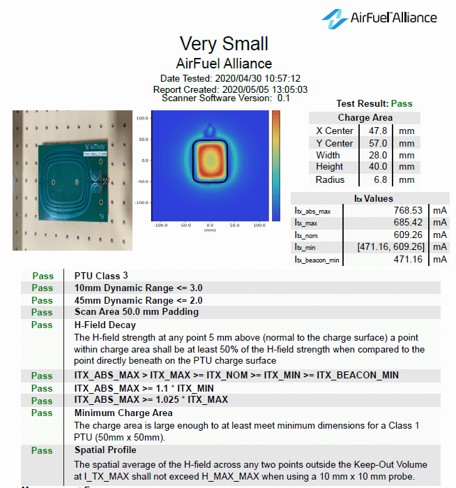
 The scanner tool creates this map and the plot. This plot is put into another piece of software that we have – and this software is available for AirFuel members to download. We’re releasing it shortly.
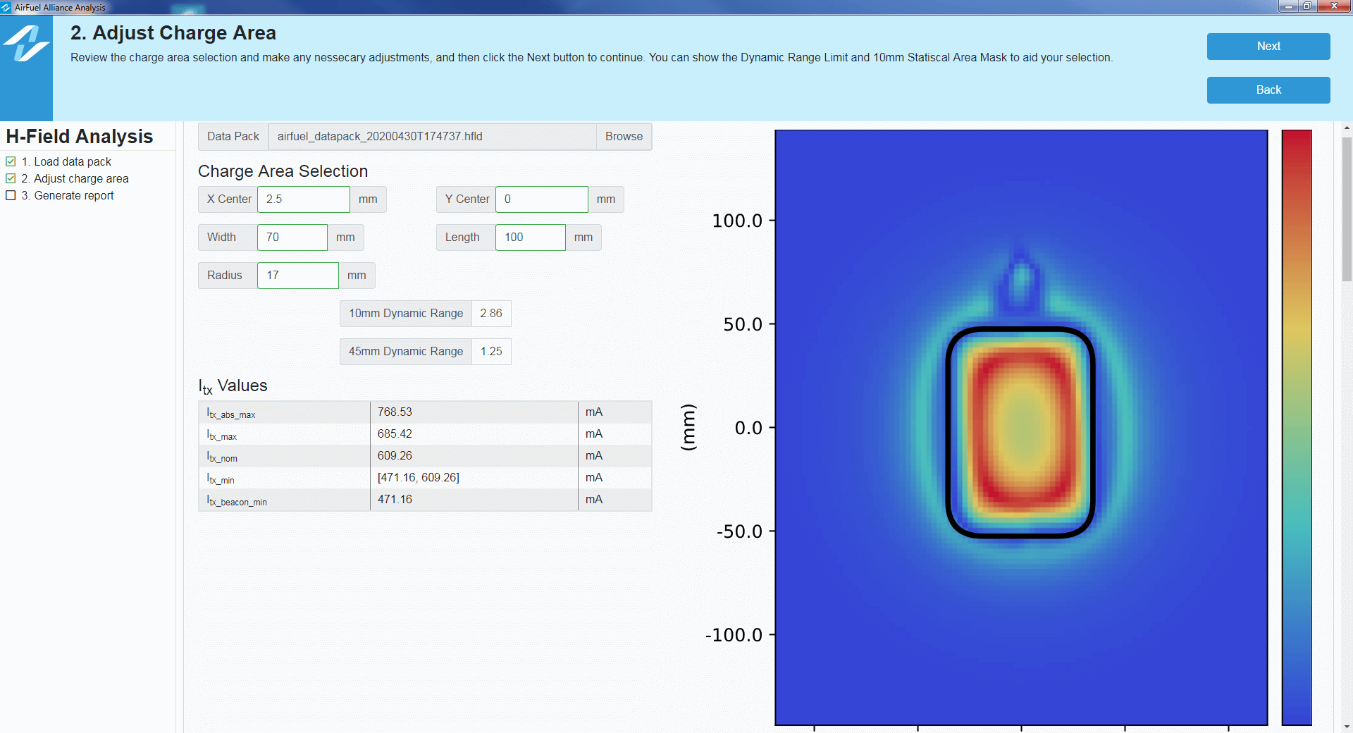
You load this file that’s been created with the scanner, and it’s three short steps. Once you load the file, you adjust the charge area if you want to. It has an automated selection that tries to meet the criteria for you. If you want to figure out what-if scenarios you can also do that. Then you simply print the report.
 This report has sufficient data for others to use, as well as for our certification authority, to understand that your resonator meets the criteria. More importantly, from a design perspective, the report allows you to understand what currents are in your system, and what currents you need to drive from your power amplifier, as well as through your coil. This is very simple software and we’re delighted to offer it to you.
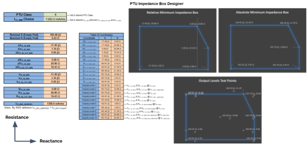
PTU Resonator Impedance Box
We characterized our current levels for the H-field that’s needed, and that was a very simple step using our H-field scanner. What about the range of impedances that will be seen by the power amplifier? This is the second part of the step that you really need to answer in order to design your electronics to drive it.
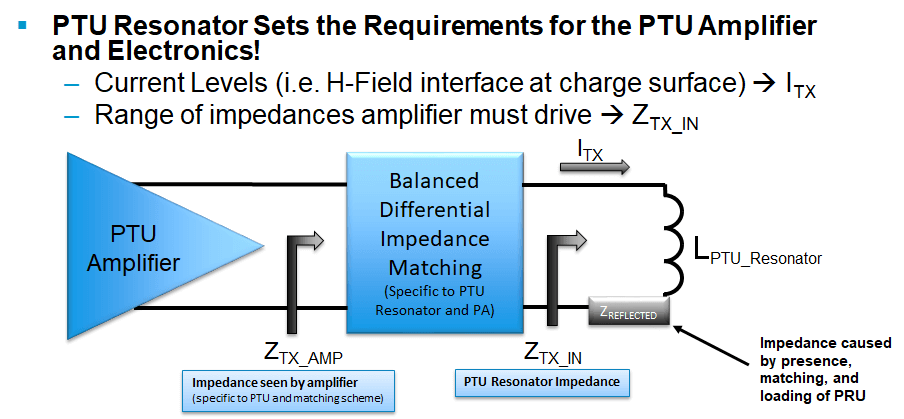
We have some very simple tests using a vector network analyzer, and two very simple devices that are placed on top of the PTU resonator and measured. This allows us to predict the range of inductive shift that’s seen at the PTU resonator coil, as well as predict the reflected impedance, which is what the PRU is doing in terms of power back to the PTU resonator. Now, once you know the impedance range here at the PTU resonator coil, which we call ZTX_IN or ZTX, you can design everything back here towards the IMN and amplifier.
Everything behind this line of ZTX is considered the power amplifier, including the resonant match or the impedance matching network. So you convert that impedance based on behaviors that you want to a loading condition. For example, you can convert a capacitive shift to be inductive and vice versa. Or you can have a one-to-one relationship. All of this is done by using magnetic resonance reactive matching. Your amplifier now powers that range of impedances, and we can test that. We test it with picking out a few points of the impedance box.
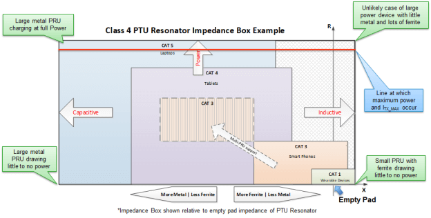
This is a classic impedance box. Although we put reactance along the X axis and resistance along the Y axis, it’s a little unconventional, but there’s a reason for that. It’s a little easier to visualize in this case.
So the vertical axis line is zero (relative reactance at PTU resonator coil). That’s your coil standing all by itself, not powering anything, just providing a little current, but no power to a receiver device. As you increase the power, you go up the impedance box (i.e., increase resistance). As you place metal on the device, you go to the left (i.e., decrease reactance). And as you put ferrite on, you go to the right (i.e., increase reactance). So this represents the range of impedances that will be seen by your power amplifier. And we understand that based on the PTU class or the power level that you select, your amplifier will have to drive more or less. So for a designer, it simply takes two inputs once you run through these PTU resonator tests. The inputs are PTU class and ITX_MIN within a range, you get to choose, and it sets your impedance box. You then pick several points for testing, and you test your amplifier at those points.
The I-H-V Relationship
How the system works is based on the I-H-V relationship. And this I-H-V relationship is really important to the H-field specifications that we have today. You can read this new specification, and you can design everything you need without seeing any other devices, by means of this specification.
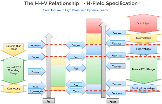
On the left hand side, moving from left to right, you have a range of operation. There are really three modes of operation in a simplistic view. One is the connecting. This is when you start to communicate between your PTU and PRU. Your Bluetooth LE comes up, and they start communicating to each other to explain what the needs of the system are. Once that occurs, the current comes up and you’re in your normal PTU operating range. So this connecting corresponds with ITX_BEACON_MIN, we call it, and it sets your connecting range.
The current in the PTU resonator then increases between MIN and MAX, and that’s the range where your PRU has to operate. Then we have an ABS MAX condition, which allows for more spatial freedom if you’d like, but you have to make sure you don’t over-voltage your PRUs in a condition that they don’t like. You operate within some safe conditions.
The current corresponds to a field level, and there’s two parts that create the field level. One is the geometry of the coil. So this is where your PRUs are positioned within that coil. Although with the new H-field specification, it’s going to be fairly constant, because that’s what we’re optimizing for – a fairly constant field in a range – you have spatial freedom. And then the current itself creates a field. This induces ,using Faraday’s law, a voltage on the PRU. And the PRU has several ranges. It’s normal range, it’s high voltage range, it can still power, but it would like to be a little less and have it be brought down to its optimal range. You then have over-voltage and out-of-spec conditions. Now with the AirFuel ecosystem, the user never knows anything is happening behind the scenes. The device is always being powered when you place the device and it connects.
Build a PRU Resonator Coil Design With AirFuel
But you might be asking, “What about the PRU? Is it easy to design these coils?” It turns out you can use simple analytical models. We’ve created a handy webpage called Build With AirFuel.
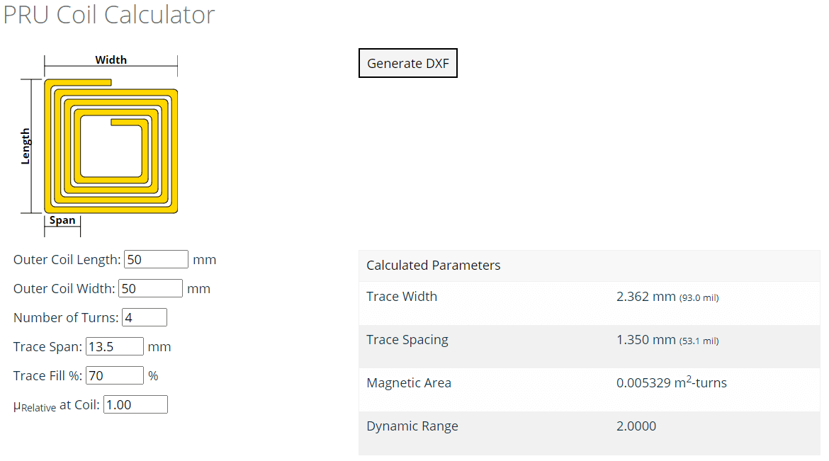
And with the tools on the site, you can determine what kind of induced voltages you would see at a coil, based on the H-field levels and the specification. With this coil (as shown on the website), you have some width, length, and span, and you can choose the number of turns within that span. In this case, I want to optimize by giving the widest coil possible for this particular design. In this case, 50 x 70 millimeters is reasonable. That would be a large tablet or phone, or something similar.
We can have a smaller span. If we look at the trace width and spacing that it creates, we can optimize Q and get the magnetic area up. You simply enter in the desired span. Then there’s the trace fill, which is how much percentage of trace width to spacing there is. Then finally, your relative mu (μ) or permeability at the coil. If you add ferrite, this can go up, and when it’s put behind metal, it may go back down. One is for free-space or an air coil, and oftentimes it can be close to one, depending on your particular design with ferrite. As we do this, we scroll down and look at the voltage induced at an open circuit coil terminal.
We will be adding some visualization features in the future, but this gives you an idea of what your voltage range will be in the worst case scenario. In maximum conditions, when the current is at its highest and you’re coupled the most, this (Absolute Max Voltage) is your peak AC. Then in the minimum condition (Min Boot Voltage), this lower voltage is what you’re going to see when starting up the Bluetooth LE. We can look at these values and say, “For our design, that’s a little higher than we would like,” so we would decrease the number of turns. We can say, “Okay, that gives us thicker traces as well, and some spacing.” We can adjust it as needed. Once we’re satisfied with the general design, this gets us started for prototyping right away. We can generate the DXF and save it.
You can import it into your favorite coil calculator, like a magnetic simulator, or just print it out as a PCB. You can take the DXF output of the PRU resonator coil design generated on the website and have it fabricated to test your concepts. You can do a few of these very quickly. We’ve added some additional explanation down below, and you can read that in your own time. You can also jump on the Build With AirFuel website to learn more. We’ll be adding more features over time, but right now it’s a handy tool you can use to get started. It shows you how simple wireless power can be.
Q&A
“How can we characterize the bounds of PRUs with so many different types of unique use cases that can shape the magnetic field in unpredictable ways?”
Those use cases are fairly niche, and this calculator is a great start. But in other cases, where you really want to understand whether your PRU works, we use five PTU test resonators based on these H-field standards. We’ve scanned these and characterized them, then tweaked them a little bit to give worst case conditions. We formulated how the field shape goes, to make sure all of those boundary conditions are there for you.

These are available to download by AirFuel members. You can download the fabrication package, or order them through our automated test system partner. We characterized them previously with a small 10-millimeter coil, this is our probe that we’ve developed that characterizes the H-field. We also characterized the PTU resonators with a 45 millimeter probe, which is a little bit more typical in terms of PRU coil size, and showed exactly what the behavior will be in the larger test cases.
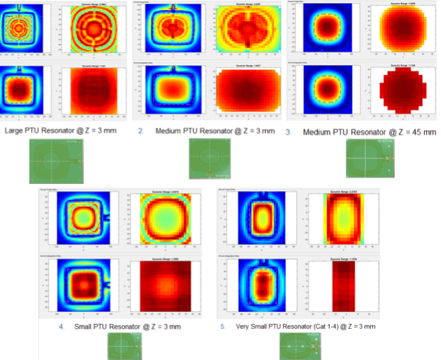
Both of these probe conditions are used to calculate what the current should be for a given PTU resonator. You can look at the field profiles and see different inflections and characteristics that are used to make sure your PRU works. Even if your simplistic view of the coil and induced calculator doesn’t get you 100% of the way, using these PTU resonator coils definitely will. You can import them in your systems, or just get a vector network analyzer and test it directly to predict what the impact is going to be.
This is a very small sampling of the tools and test tools that we provide in AirFuel. We also have a PRU full simulator, so you can automatically import some measured information using a vector network analyzer into this tool. You can adjust your matching conditions to see if you meet the AirFuel specification and what to expect with each of these five PTU resonators. We also have a full suite of automated test systems for conformance and interoperability. This is just the tip of the iceberg – there’s a lot more, and we would love to have you join AirFuel to both contribute and to obtain these tools and information.

“Can you give a ratio of heating of metal objects between Qi and AirFuel? How many times is it less?”
Basically, if you take 6.78 million and divide it by 100,000, the square root of that (i.e., ~ 8x less) is roughly what you will see, in terms of metal heating. But it does depend on the application a bit. It turns out that induction requires pretty high field levels between the coils, so there’s a significant savings in terms of metal heating using AirFuel magnetic resonance at 6.78 MHz.
“With the H-field solution, when the receiver is placed on the transmitter, the H-field will likely change its shape. How do you predict this change? Or how does the standard address that?
With very simple coils, you can use a simple analysis. In the case of changing shape, the classic example is a very small coil with a very large metal back. That decreases the coupling in the center, when you think it might actually increase it. We do have ways to test this – we’ve bounded them using the 5 H-Field PTU resonator designs and testing.
“Do you have to use gallium nitride when building AirFuel systems?”
There are a lot of advantages to gallium nitride in the operation at 6.78 MHz, but it is not required. There are plenty of systems that don’t use gallium nitride. They use silicon devices. This may work to some extent, but are a lot of advantages to gallium nitride. I would definitely point to EPC and some of their wisdom for this question. I think they have some webinars and resources on the topic.
“Could you clarify the concept of PRU categories and PTU classes?”
The categories and classes really aren’t that difficult. It really is just saying, “How much power do you expect to draw?” If I’m a phone and I need to draw 5 watts, I’m going to be a category 3. If you need to draw 5W and up to 6.5 watts, we call that a category 3 device. Now the question is, which PTUs can I place this on? And the answer is any PTU from class 2 to class 6.
So if you take the PRU category number, category 3, and subtract one, you should be able to power on that PTU class (i.e., class 2) and above. This doesn’t change the PTU resonator design. What this changes is the power amplifier design on the PTU, and how much power I can deliver. Categories and classes are just to make sure that you’re not placing a laptop on something small that’s only meant to charge phones and wearables and feature type devices, whereas the higher classes of PTUs can really power anything in the AirFuel ecosystem.
“What is the frequency range of AirFuel, and how tight does it have to be around 6.78 MHz? Or does it have some freedom, like Qi does?”
With AirFuel magnetic resonance, we don’t rely on frequency sweeping to do optimization. At 6.78 MHz, there are some regulations that we follow to be within the ISM band. I believe we want to be within plus or minus 15 kHz (30 kHz bandwidth). But in essence, we hold the frequency constant and we adjust other things instead. This really allows for optimized experience and prevents interference of devices that can be seen in other cases or standards.
“Will load on a PRU – for example, the environment in which the PRU is installed such as different chassis material and so on – affect the matching as seen by the amplifier?”
When you’re doing resonant matching, what you need to know is a range of inductances that your receive or transmit coil will experience. So yes – metal and ferrite affects that range of inductance. This is accounted for in our testing and setup there. You’ll definitely want to account for that information, but it is accounted for with respect to that impedance box on the PTU resonator side. Or on the PRU side, you usually don’t get a lot of shift from the PTU. We ensure that’s the case in our testing, but we’ll get some from the device itself. When you’re testing, you test inside the device, as it is.
“Can you tell me a little bit more about the tool that gives the impedance box with the PTU class and given, I’m assuming, the transmitter coil current?”
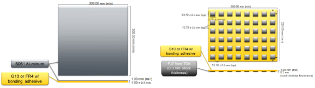
With respect to a PTU resonator box tool, it’s very simple. We have two tools – one that tests the shift in the capacitive (negative) direction, and another that tests the shift in the inductive (positive) direction. It is an aluminum plate of a certain size, with a spacing, and we place that on the PTU resonators.
With consumer devices, most of the reactance induced is because of this passive shift when you place metal or ferrites in the region. We give some allowance for what I call the active shift or the power and reflective impedance that’s provided from the PRU. Now you have your impedance box.
On the inductive (positive) side we simply use a sheet of FR4 with some ferrite tiles that are placed in a configured pattern. We did a lot of experimentation to come up with these very simple tools, and they’re available for purchase from our automated test system vendors. Of course, the specifications for them are available for our members as well.
In Summary
AirFuel Resonant wireless power is the next generation of wireless power for all of your devices. AirFuel magnetic resonance provides a much better consumer experience by offering spatial freedom, simultaneous powering of multiple devices, and allowing a wide variety of devices from wearables to phones, tablets, and laptops without compromising efficiency.
Join us at the AirFuel Alliance – cutting the cord and powering the next generation of smart devices! Contact us about membership.
Interested in wireless power?
Innovation in wireless power is moving fast. To stay up to date on the latest in wireless power and AirFuel Alliance events, sign up for our email list below.